
MODELS - The ROM4 SPLINT
About the ROM4 Model
The ROM4 is an update to the previously prototyped ROM2 splint that adds control to some of the rotational DOF (Degrees of Freedom) governing the shoulder and scapula. The main assemblies and components it comprises are labeled in the first picture in the slideshow below. Overall, there are six DOF that the arm and shoulder are permitted to move in and that can be controlled, including:
-
forearm supination/pronation*
-
shoulder flexion/extension*
-
shoulder adduction/abduction*
-
shoulder internal/external rotation*
-
elbow flexion/extension
-
scapular elevation/depression.
*The number "4" represents the number of primary axes that can be controlled and are controllable by knobs.
The splint allows the arm and shoulder to either be locked in these DOF at a selected angle or be free to move. The knobs rotate gears coupled to each DOF and hold the arm and shoulder in place as they're being rotated. There is a clutch for each of the four primary axes that is used to switch the corresponding DOF between a state of being locked and a state of being free to move.
Clutches, Locks, and Knobs
-
The flexion-extension clutch is a dog clutch that is engaged by rotating a handle while flexing or extending the shoulder to line up the teeth as they try to engage. It is disengaged by rotating the handle in the opposite direction.
-
The adduction-abduction clutch is a dog clutch that is engaged by pulling a pin, rotating it 90 degrees, releasing it into the lower slot, and adducting or abducting the shoulder to line up the teeth so they can engage. It is disengaged by pulling the pin, rotating it 90 degrees, and releasing it into the upper slot.
-
The internal-external rotation clutch is a dog clutch that is engaged by translating it while internally or externally rotating the shoulder to line up the teeth as they try to engage. It is disengaged by shifting the clutch in the opposite direction.
-
The supination-pronation clutch is a screw clutch that is engaged by supinating or pronating the forearm until the thumbscrew posts are lined up and threading each thumbscrew into its corresponding post.
-
The elbow's range of flexion or extension can either be limited or locked at a number of discrete angles. It is limited by engaging the flexion hinge selector pin with a hole that corresponds to the desired max flexion angle and engaging the extension hinge selector pin with a hole that corresponds to the desired max extension angle. It is locked by engaging the hinge lock pin with a hole that corresponds to the desired angle within the range permitted by the flexion and extension hinge selector pins.
-
Each of the three pins is part of a part of a retractable spring plunger assembly. The hinge lock pin can be locked in the disengaged position by pulling it, rotating it 90 degrees, and resting the cap on the grooves.
-
The flexion and extension hinge selector pins are not lockable in the disengaged position.
-
-
The scapular rotation lock knob is engaged by rotating it until it becomes tight and disengaged by loosening it. The main purpose for engagement is to be able to lock the scapula at a desired angle of elevation or depression. When disengaged the shoulder is free to shrug and relax and movements that involve scapular elevation and depression are permitted.
-
The scapular hinge lock knob is engaged by rotating it until it becomes tight and disengaged by loosening it. When disengaged, the flexion-extension assembly can pivot. The main purpose for disengagement is for the assembly to be able to tilt as the arm is being raised or lowered (which causes scapular elevation or depression), which allows the assembly to perform its function without intersecting the body.
How the Splint is Worn
The splint is worn by putting on and securing the torso vest with straps. First, the affected arm is passed through the armhole of the vest, through the opening of the shoulder sleeve, and through the opening of the wrist cuff. The upper and lower halves of the wrist cuff are then squeezed together against the wrist and forearm. The clamping pressure is held by a ratchet locking system. This system is designed to make putting on the cuff quick and easy. The overall design of the splint is intended to make it easy for the wearer to put on without assistance (assuming the presence of another sufficiently functioning arm) by obviating straps and fasteners that are difficult to reach or fasten. Additionally, the positional adjustment of each DOF is made to be doable with one hand and most of the knobs are in the same general vicinity.
The torso vest, the shoulder sleeve, and the wrist cuff are all components that are molded based on the wearer's body for a streamlined and accurate fit. The interior of the shoulder sleeve progresses from being molded to the shape of the shoulder to being cylindrical to accommodate the upper arm's internal and external rotation within the sleeve. Because the torso vest hugs the upper body, the majority of the splint's weight is borne by the torso. Unlike many splints that attach to the upper arm by means of straps and clamping pressure, using the torso vest means that high clamping pressure on the upper arm is not needed for attachment, which eliminates unnecessary friction, rubbing, and hindering of circulation. Because of the distribution of weight, wearing the splint for long periods of time is much more feasible.
The position of the upper splint arm is adjusted so that the axis of the elbow flexion-extension disks is coincident with that of the elbow. The remaining components and assemblies are configured to have their axes coincide with their corresponding joints.
The position of the supination-pronation gearbox along the lower splint arm is adjusted to move the wrist cuff to the desired position. The ideal wrist cuff position is such that the edge closest to the hand is situated just above the pisiform bone because the best grip for supination or pronation is achieved by clamping the carpel bones. The radius and ulna twist, untwist, and shift during supination and pronation, but the carpal bones of the wrist remain fixed. Additionally, clamping too far above the pisiform makes it difficult for the wrist to flex and extend.
Design Elements
The design of the splint is modular so that components or assemblies that need to be replaced are easily replaced. It also simplifies the manufacturing process.
The torso vest is semi-flexible to permit scapular motions such as protraction and retraction, although there are no mechanisms built in to control them. The scapular rotation rail housings, however, are rigid so that the scapular rotation rails can slide smoothly and without hindrance.
By engaging a select combination of clutches and knobs, rehabilitative exercises can be facilitated and adaptations made to perform certain movements. Several examples of this are illustrated in the animations below, in addition to the splint's basic functionalities. It is seen that almost any anatomical configuration of the arm and shoulder, both static and dynamic, can be achieved. The hope is that after rehabbing with the splint on, the same motions can be executed as closely as possible with the splint off and the splint will no longer be necessary. This would be an ideal case, however, and the capacity for rehabilitation is dependent on the extent and nature of the injury. In any event, whatever can't be recovered through stretches and exercises, the splint helps adapt to performing desired movements. It's all about the wearer making the best possible uses of the motions they have by using the splint to supplement what's missing.
Configurable Design Elements
With each splint being molded to the wearer's body, it is anticipated that additional customizations might be needed for their nuanced and individual needs. Certain customizations, if applicable to a wide base of people, might lead to changes to the base design. The ROM4 lets four primary axes be controlled by knobs and is the most general and versatile version to date. New models within the ROM splint series may be created by configuring what DOF are permissible and whether or not they can be controlled and locked. A ROM3 splint, for example, might permit the same DOF as the ROM4 except wouldn't allow flexion or extension to be controllable. This might apply to someone who only intends to use the splint for running, as depicted in the first animation below, and thus wouldn't ever need to lock the flexion-extension angle. In this instance, eliminating the flexion-extension clutch components would streamline the model. Additionally, the modularity even allows new models to be created based on what assemblies and components are swapped out.
Pictures
CAD Model
 Front View with Main Assemblies and Components Labeled | 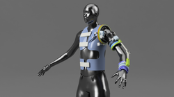 Front Right Perspective View |  Right Side View |
|---|---|---|
 Back Right Perspective View | 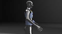 Left Side View |  Top View |
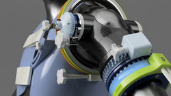 Front Perspective Close-up |  Front Perspective Close-up |  Top Perspective View |
 Back Perspective Close-up |  Front Close-Up |  Forearm Perspective Close-up |
 Elbow Flexion-Extension Disks Close-up |  Front Right Perspective View |  Right Side View |
 Top View |  Front Perspective Close-up |  Front Perspective Close-up |
 Top Perspective View |  Back Perspective Close-up |  Front Close-Up |
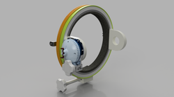 Front Right Perspective of Flexion-Extension Assembly Coupled to Adduction-Abduction Assembly |  Front Left Perspective of Flexion-Extension Assembly Coupled to Adduction-Abduction Assembly |  Back Left Perspective of Flexion-Extension Assembly Coupled to Adduction-Abduction Assembly |
 Back Right Perspective of Flexion-Extension Assembly Coupled to Adduction-Abduction Assembly |  Front Right Perspective of Shoulder Sleeve Assembly Coupled to Internal-External Rotation Gearbox Assembly |  Front Right Perspective of Shoulder Sleeve Assembly |
 Back Right Perspective of Shoulder Sleeve Assembly |  Bottom Front Perspective of Shoulder Sleeve Assembly |  Bottom Rear Perspective of Shoulder Sleeve Assembly |
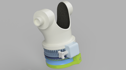 Front Right Perspective of Shoulder Sleeve Assembly Coupled to Internal-External Rotation Gearbox Assembly |  Front Right Perspective of Shoulder Sleeve Assembly |  Back Right Perspective of Shoulder Sleeve Assembly |
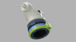 Bottom Front Perspective of Shoulder Sleeve Assembly |  Bottom Rear Perspective of Shoulder Sleeve Assembly |  Top Right Perspective of Wrist Cuff Assembly |
 Bottom Left Perspective of Wrist Cuff Assembly |  Wireframe View |  Artistic Abstraction with Manikin |
 Artistic Abstraction without Manikin |
Working Model
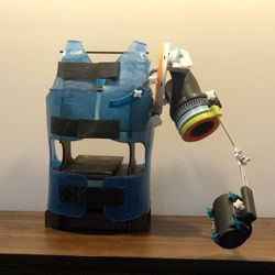 Front View |  Front Right Perspective View | 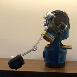 Left Side View |
|---|---|---|
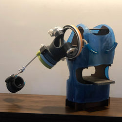 Rear Right Perspective View | 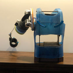 Rear View | 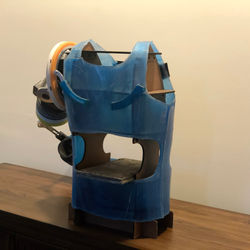 Rear Left Perspective View |
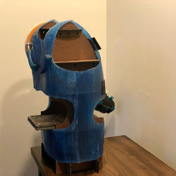 Rear Left Perspective View | 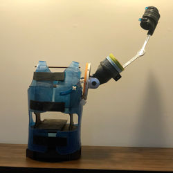 Front View - Arm Raised | 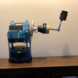 Front View - Arm Raised and Elbow at 90 Deg |
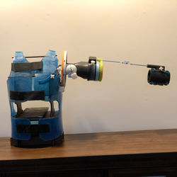 Front View - Arm Horizontal | 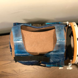 Top View | 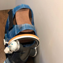 Top Right Perspective View |
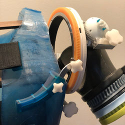 Front Close-up | 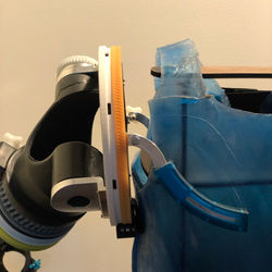 Rear Close-up | 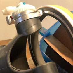 Shoulder Sleeve Assembly Close-up |
 Front Close-up | 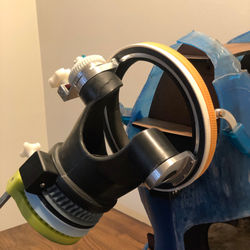 Shoulder Sleeve Assembly Close-up | 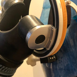 Rear Close-up |
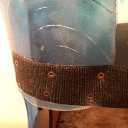 Torso Vest Strap Close-up | 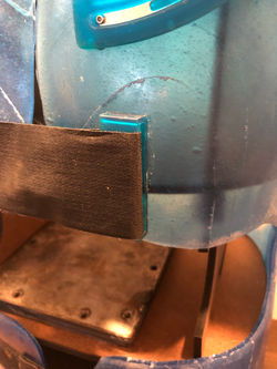 Torso Vest Strap Loop Close-up | 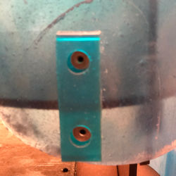 Torso Vest Strap Loop Close-up |
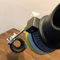 Arm Close-up | 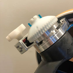 Adduction-Abduction Gearbox Close-up | 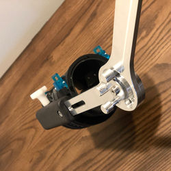 Forearm Close-up |
 Elbow Flexion-Extension Disks Close-up |  Elbow Flexion-Extension Disks Close-up |  Wrist Cuff Assembly Close-up |
 Wrist Cuff Assembly Close-up | 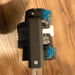 Wrist Cuff Assembly Close-up |
Animations
CAD Model
The ROM4 Splint - Running Motion


The ROM4 Splint - Running Motion

The ROM4 Splint - Shoulder Internal/External Rotation

The ROM4 Splint - Forearm Supination/Pronation

The ROM4 Splint - Shoulder Adduction/Abduction (Clutch Engaged)

The ROM4 Splint - Shoulder Adduction/Abduction (Clutch Disengaged)

The ROM4 Splint - Shoulder Flexion/Extension

The ROM4 Splint - Overhead Reach

The ROM4 Splint - Guitar Strumming Motion

The ROM4 Splint - Violin Bowing Motion

The ROM4 Splint - Bicep Curl Progressive
Working Model
The ROM4 Splint - Shoulder Flexion/Extension Knob


The ROM4 Splint - Shoulder Flexion/Extension Knob

The ROM4 Splint - Shoulder Internal/External Rotation Clutch Engaged/Disengaged

The ROM4 Splint - Shoulder Adduction/Abduction Clutch Disengagement/Engagement

The ROM4 Splint - Shoulder Adduction/Abduction Knob

The ROM4 Splint - Arm Raise

The ROM4 Splint - Shoulder Raise and Flexion/Extension Assembly Pivot

The ROM4 Splint - Flexion/Extension Clutch Rotation

The ROM4 Splint - Elbow ROM Adjustment

The ROM4 Splint - Forearm Supination/Pronation Knob

The ROM4 Splint - Wrist Cuff Assembly Spring Action

The ROM4 Splint - Wrist Cuff Assembly - Clutch Disengagement
